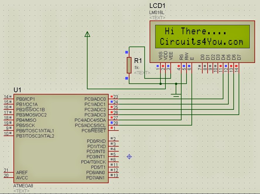
In this tutorial you will learn how to interface 16x2 LCD display and similar LCDs with Atmega8 Microcontroller. You will see that how to interface LCD using only 6 IO lines. details about LCD commands and other techniques are explained in 8051 LCD interfacing tutorial present in 89C51 tutorial section.
Objective:
1. To use minimum IO lines to interface LCD.
2. We are using 6-IO Lines
3. To control display on which line it should display
4. Use of minimum components
Circuit Diagram :
C Code, Program (AVR Studio 4):
//=================================================================
/* 4-Bit mode 16x2 LCD Module Software      */
/* 2nd Dec 2005                             */
/* Copyright 2005 Circuits4You.com          */
/* WWW - http://www.circuits4you.com        */
/* Email - info@circuits4you.com            */

/* LCD Pin-5(R/W) must be connected to ground*/
//=================================================================
#include <avr/io.h>
#include <string.h>

#define E   PC5
#define RS   PC4

void display(char string[16], char LineNo);
void displaybyte(char D);
void dispinit(void);
void epulse(void);
void delay_ms(unsigned int de);

//=================================================================
//        Main Function
//=================================================================
int main(void)
{
 DDRC = 0x03F;  //Set LCD Port Direction

  delay_ms(500);  //Initiaize LCD
  dispinit();
  delay_ms(200);
 display(" Hi There....",1);
 display("Circuits4You.com",2);
  while(1);
}

//=================================================================
//        LCD Display Initialization Function
//=================================================================
void dispinit(void)
{
 int count;
 char init[]={0x43,0x03,0x03,0x02,0x28,0x01,0x0C,0x06,0x02,0x02};

 PORTC &= ~(1<<RS);           // RS=0
 for (count = 0; count <= 9; count++)
  {
 displaybyte(init[count]);
  }
 PORTC |= 1<<RS;    //RS=1
}


//=================================================================
//        Enable Pulse Function
//=================================================================
void epulse(void)
{
 PORTC |= 1<<E;
  delay_ms(1); //Adjust delay if required
 PORTC &= ~(1<<E);
 delay_ms(1); //Adjust delay if required
}


//=================================================================
//        Send Single Byte to LCD Display Function
//=================================================================
void displaybyte(char D)
{
 //data is in Temp Register
  char K1;
  K1=D;
  K1=K1 & 0xF0;
  K1=K1 >> 4;  //Send MSB

  PORTC &= 0xF0;
  PORTC |= (K1 & 0x0F);
 epulse();

  K1=D;
  K1=K1 & 0x0F;  //Send LSB
        PORTC &= 0xF0;
  PORTC |= K1;
 epulse();
}

//=================================================================
//        Display Line on LCD at desired location Function
//=================================================================
void display(char string[16], char LineNo)
{
 int len,count;

 PORTC &= ~(1<<RS);           // RS=0 Command Mode

 if(LineNo==1)
 {
  displaybyte(0x80);   //Move Coursor to Line 1
 }
 else
 {
  displaybyte(0xC0);   //Move Coursor to Line 2
 }
 PORTC |= (1<<RS);           // RS=1 Data Mode

        len = strlen(string);
   for (count=0;count<len;count++)
  {
    displaybyte(string[count]);
 }
}


//=================================================================
//        Delay Function
//=================================================================
void delay_ms(unsigned int de)
{
unsigned int rr,rr1;
   for (rr=0;rr<de;rr++)
   {

  for(rr1=0;rr1<30;rr1++)   //395
  {
   asm("nop");
  }

   }
}
For queries comment...


will you plzz provide the circuit diagram above given is not opening plzz
ReplyDeletevrushalnanavati73@gmail.com is my mail
please can you send the code to my gmail
ReplyDeletespatruni2@gmail.com