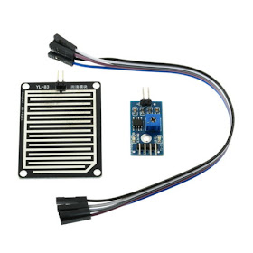
Prepared for the rainy season? No ? How about a little help with the Arduino? Use a rain sensor like this photo below, so you can close a window when you're not at home or drive a pump to store rainwater. or operate wipers of car windshield.
If you want to test only the sensor, without mounting the entire circuit, the values are also displayed in the serial monitor.
The rain sensor for Arduino is a component with two parts: the sensor plate formed by several tracks resistant to oxidation, which will detect the liquid level is reached the plate and the module with LM393 comparator chip, which is responsible for reading the information from this sensor and send the data by pin A0 (analog) or D0 (digital - values 0 and 1) . This module also has a potentiometer for sensitivity adjustment, a red lED for indicating oN , and green lED indicates that data transmission:
I quoted at the beginning of the post, you can use a motor connected to the digital output to open (no rain - level HIGH) or close (with rain - level LOW) a window when rain is detected, and the analog output you can open a valve or trigger a pump depending on the intensity of the rain, reading the values from 0 to 1023 provided by this port. Test your module with only 3 leds and 3 resistors, riding the circuit below.The module can be supplied with voltages of 3.3 volts to 5:
The test program reads the sensor information and illuminates the LEDs according to the liquid level detected by testing the values read in a series of commands IF (IF), which can be added or modified in accordance with the level of accuracy desired.
// Program: Rain Sensor Test
// Author: blog.circuits4you.com

int pino_d = 2 ; // pin connected to D0 sensor
int pino_a = A5; // pin connected to A0 sensor
int val_d = 0 ; // Store the value read from the digital pin
int val_a = 0 ; // Store the value read from analog pin

// Ports connected to the LED
int pin_led_high = 5 ;
 int pin_led_medium = 6 ;
 int pin_led_low = 7 ;

void setup ()
{
  // Set the pins on the sensor as input
  pinMode (pino_d, INPUT);
  pinMode (pino_a, INPUT);

  // Set the pins of LEDs as output
  pinMode (pin_led_high, OUTPUT);
  pinMode (pin_led_medium, OUTPUT);
  pinMode (pin_led_low, OUTPUT);
  Serial.begin ( 9600 );
}

void loop ()
{
  // Le arnazena and the value of the digital pin
  val_d = digitalRead (pino_d);
  // Le and stores the value of the analog pin
  val_a = analogRead (pino_a);
  // Send the information to the serial monitor
  Serial.print ( "Digital Value" );
  Serial.print (val_d);
  Serial.print ( "- Value Analog" );
  Serial.println (val_a);

  // Turns on the LED according to the intensity
  if (val_a> 900 && val_a < 1024 )
  {
    // Lights LED green - low intensity
    digitalWrite (pin_led_high, HIGH);
    digitalWrite (pin_led_medium, LOW);
    digitalWrite (pin_led_low, LOW);
  }
  if (val_a> 400 && val_a < 900 )
  {
    // Lights LED yellow - moderate
    digitalWrite (pin_led_high, LOW);
    digitalWrite (pin_led_medium, HIGH);
    digitalWrite (pin_led_low, LOW);
  }
  if (val_a> 0 && val_a < 400 )
  {
    // Turns on Red LED - High intensity
    digitalWrite (pin_led_high, LOW);
    digitalWrite (pin_led_medium, LOW);
    digitalWrite (pin_led_low, HIGH);
  }
  delay ( 1000 );
}
If you want to test only the sensor, without mounting the entire circuit, the values are also displayed in the serial monitor.


No comments:
Post a Comment