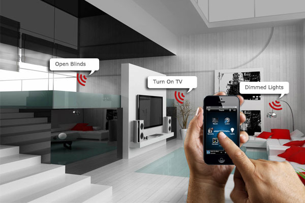
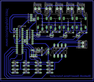
Bluetooth based home automation, project allows you to control electrical appliances using your android mobile phone. It consists of ATmega8 microcontroller, HC-06 Bluetooth module, Relays.
Step 5: Test the code and Hardware
1. Install Android app on your phone.
2. Allow third party download
3. Pair HC-06
4. Then start the software
5. Follow us on Google+
6. You Did it Yourself
7. Refer Tutorials from this site for more understanding of code and Circuits
There are many Home Automation Systems available in our market. Most of these are simple home appliances controlling systems like DTMF controlled home Appliances, IR Remote based home appliances controlling, RF based home appliances controlling. we are going to discuss about Bluetooth based Home/Office Appliances Control (Home Automation System).
Here all circuit details with PCB design, Code and Android application are provided.
Features:
1. Control your home electrical appliances using smart android phone.
2. Simple easy to use Android App to control your devices.
3. Uses Standard Bluetooth Module HC-06.
4. Digital Switches are provided for manual operation.
5. Low Cost.
1. Control your home electrical appliances using smart android phone.
2. Simple easy to use Android App to control your devices.
3. Uses Standard Bluetooth Module HC-06.
4. Digital Switches are provided for manual operation.
5. Low Cost.
Step 1: Components Required
1. Atmega 8 Microcontroller
2. Relays
1. Atmega 8 Microcontroller
2. Relays
3. ULN2003
4. LM7805
5. BC548
6. 1K Ohm Resistors
7. Bluetooth Module
4. LM7805
5. BC548
6. 1K Ohm Resistors
7. Bluetooth Module
8. Buzzer
Step 2: Circuit Design and PCB Manufacturing
Step 3: Programming the controller
AVR Studio C Code
/*********************************************************************************/
/*       Bluetooth based home automation                      */
/*   www.circuits4you.com               */
/*   blog.circuits4you.com               */
/*********************************************************************************/
#include <avr/io.h>
#include <string.h>
#include <avr/interrupt.h>
//Relay Connection
#define D0   PC1
#define D1   PC2
#define D2   PC3
#define D3   PC4

//Switches Connection
#define S1  PB1
#define S2  PB0

#define S3  PB2
#define S4  PD7

#define S5  PB3
#define S6  PD6

#define S7  PB4
#define S8  PD5

//Declaration
unsigned char u8_data;
void delay(unsigned int de);
void USART_Init();
void Process();

/*********************************************************************************/
/*         Main Routine                                 */
/*********************************************************************************/
int main(void)
{
 delay(100);
 DDRB = 0b00011111;
 PORTB = 0b00011111; //Enable internal pullups for switches
 DDRD = 0b11100010;  //Enable internal pullups for switches
 PORTD = 0b11100000;
 DDRC = 0b00011110; //Relay port directions

 //Enable Interrupt
 USART_Init();
 SREG=0x80;
 delay(100);

 while(1)
 {
  Process();
 }

}

/*********************************************************************************/
/*         Delay of 1mSec                               */
/*********************************************************************************/
void delay(unsigned int de)
{
unsigned int rr,rr1;
   for (rr=0;rr<de;rr++)
   {

  for(rr1=0;rr1<30;rr1++)   //395
  {
   asm("nop");
  }

   }
}

/*********************************************************************************/
/*         RS232 Intitialize                            */
/*********************************************************************************/
void USART_Init()
{
/* Set baud rate */
 UBRRH = 0x00;  //9600 @ 8MHz
 UBRRL =103;
//Set double speed
  UCSRA |= (1<<U2X);
/* Enable receiver and transmitter */
 UCSRB = (1<<RXEN)|(1<<TXEN);
/* Set frame format: 8data, 2stop bit */
// UCSRC = (1<<URSEL)|(1<<USBS)|(3<<UCSZ0);
//Set interrupt on RX
  UCSRB |= (1<<RXCIE);
}

/*********************************************************************************/
/*         RS232 Interrupt                              */
/*********************************************************************************/
SIGNAL(USART_RXC_vect)
{
 u8_data=UDR;
 switch(u8_data){
 case 0x03:
  PORTC |= (1<<D0);  //Relay 1 On
 break;
 case 0x04:
  PORTC &= ~(1<<D0);  //Relay 1 Off
 break;
 case 0x05:
  PORTC |= (1<<D1);  //Relay 2 On
 break;
 case 0x06:
  PORTC &= (1<<D1);  //Relay 2 Off
 break;
 case 0x07:
  PORTC |= (1<<D2);  //Relay 3 On
 break;
 case 0x08:
  PORTC &= (1<<D2);  //Relay 3 Off
 break;
 case 0x09:
  PORTC |= (1<<D3);  //Relay 4 On
 break;
 case 0x0A:
  PORTC &= (1<<D3);  //Relay 4 Off
 break;
 case 0x0B:  //All on
  PORTC |= (1<<D0);
  PORTC |= (1<<D1);
  PORTC |= (1<<D2);
  PORTC |= (1<<D3);
 break;

 case 0x0C:  //All off
  PORTC &=~(1<<D0);
  PORTC &=~(1<<D1);
  PORTC &=~(1<<D2);
  PORTC &=~(1<<D3);
 break;
   }
 return;
}


/*********************************************************************************/
/*         Process                                      */
/*********************************************************************************/
void Process()
{
  delay(100);
//Switch 1============================================
   if((PINB & 0x02) == 0x02)
   {
    PORTC |= (1<<D0);
   }
   if((PINB & 0x01) == 0x01)
   {
    PORTC &=~ (1<<D0);
   }
   delay(10);
//Switch 2============================================
   if((PINB & 0x04) == 0x04)
   {
    PORTC |= (1<<D1);
   }
   if((PIND & 0x80) == 0x80)
   {
    PORTC &=~ (1<<D1);
   }
   delay(10);
//Switch 3============================================
   if((PINB & 0x08) == 0x08)
   {
    PORTC |= (1<<D2);
   }
   if((PIND & 0x40) == 0x40)
   {
    PORTC &=~ (1<<D2);
   }
   delay(10);
//Switch 4============================================
   if((PINB & 0x10) == 0x10)
   {
    PORTC |= (1<<D3);
   }
   if((PIND & 0x20) == 0x20)
   {
    PORTC &=~ (1<<D3);
   }
   delay(10);

}

/*********************************************************************************/
/*         END                                          */
/*********************************************************************************/
Step 4: Download Android App
1. Install Android app on your phone.
2. Allow third party download
3. Pair HC-06
4. Then start the software
5. Follow us on Google+
6. You Did it Yourself
7. Refer Tutorials from this site for more understanding of code and Circuits


Dear author,
ReplyDeleteI am very fascinated of your great project. I will use it in in my house.
Therefore I have to modify the app, but I am not very familiar in programming apps.
I am interested in the source-code and the name of your programming environment.
Would you provide these informations?
Yours respectfully
Jens
Programming environment.: Android code requires ADK+eclips
Deletehello sir ....actually I'm little bit confused with switches and android app which i downloaded how to connect my devices?
ReplyDeleteJust pair your HC-06 Bluetooth module from bluetooth settings (Not in App in your phones setting) and Then start the App , Press connect button on the App. It should show "connected". This App works only with HC-06, If you want other bluetooth module please comment
Deleteyes can you please tell it for hc-05 module.
Deletehow to add devices in android app sir would you pls exaplain it?
ReplyDeleteYou don't need to add bluetooth device in app, Pair HC-06 from bluetooth settings (your phones setting menu). App detects paired HC-06 module, If you are using other module inform me, I will send the app for that module
Deletei am using HC-O5 please send me the app link
Deletehello. I am relatively new to electronic hardware. I really like your project and the fact that you've described everything. and i am trying to replicate it for my open day project. If you could help me out i have a few questions regarding the circuit diagram.
ReplyDeleteI am trying to implement this on proteus but i can't figure out which component is which. cause this diagram differs a bit.
can you tell me what is G5L here. and what rating of relay is to be used?
and what are those parts labelled load.
and where have you used the 7805 transistor?
or can you send me its proteus file
thank you
12V Relay G5L Suger Cube relay
Deletethank you so much...it was perfect..
ReplyDeletekindly send me the link for app download plz
hello. can i get the android app for hc-05? i have this as my project and it's due monday
ReplyDeleteKindly provide android app for HC-05
ReplyDeleteis there an alterngative for atmega8? and can i use the monopod shutter as my bluetooth module? thanks
ReplyDeletehi. i'm trying to combine your gsm based fire alarm system project with gsm based home automation system. i'm trying to implement them on proteus. i couldnt find capacitor 104(0.1uf) and relay G5L.. what can i use instead of them? and what do X1,X2.... X5 mean in the circuit? are they oscillator? if yes what tyoe of oscillators are they? can i get some help? thenks in advance :)
ReplyDeleteHi guys, I set it up on breadboard but HC06 goes off after 5-6 seconds and 5V supply get hot. HC06 on its own when connected to the same 5V supply is ok. I noticed that pin 9 of mega8 is connected on the layout but not on the schematic. Could you check that for me please? Thanks
ReplyDeleteNice post
ReplyDeleteHi guys, I left a similar message about 2 weeks ago but it still not showing. On the schematic, pin 9 is not connected but on the layout it is connected. I set it up on breadboard like the schematic but it didn't work. I didn't try the layout one yet. Could you check which one is correct please? Thanks
ReplyDeletewhat software do you used to create complete circuit??
ReplyDeleteNaeem Ahmed
ReplyDeletei am using HC-O5 please send me the app link I m very thankful u
solangi01@gmail.com
Please provide hc-05 android apps
ReplyDeletecan i use arduino for this project
ReplyDeletesee arduino projects from top menu project section, arduino based home automation in 10 minutes is already posted.
Deletehello sir. . .can i connect gsm shield and bluetooth hc-06 at arduino uno in one time? i just confuse the connection can use it or not. . .
ReplyDeletehello sir. . .can i used gsm and bluetooth module at the arduino uno in one time? i just confuse that is can use it or not?
ReplyDeleteYou can connect bluetooth and GSM modem at the same time use software serial for GSM and hardware serial for Bluetooth
Deletetq sir
Deleterespected sir, is there an easy way to do the same smart yet basic home automation system with visitor counter by using the raspberry pi?
ReplyDelete