The circuit given here is of digital temperature indicator with LED 7-segment display using the ICL7107. It measures temperature from 00.0 C to 99.9 C. ICL7107 is a 3 1/2 digit A/D converters with LED 7-Segment Driver. We convert 99.9mV Voltmeter into a Temperature indicator first we design 99.9mV Voltmeter.
The Intersil ICL7106 and ICL7107 are high performance, low power, 31/2 digit A/D converters. Included are seven segment decoders, display drivers, a reference, and a clock. The ICL7106 is designed to interface with a liquid crystal display (LCD) and includes a multiplexed backplane drive; the ICL7107 will directly drive an instrument size light emitting diode (LED) display. The ICL7106 and ICL7107 bring together a combination of high accuracy, versatility, and true economy. It features autozero to less than 10μV, zero drift of less than 1μV/oC, input bias current of 10pA (Max), and rollover error of less than one count. True differential inputs and reference are useful in all systems, but give the designer an uncommon advantage when measuring load cells, strain gauges and other bridge type transducers. Finally, the true economy of single power supply operation (ICL7106), enables a high performance panel meter to be built with the addition of only 10 passive components and a display.

Working:
We have designed basic 99.9mV DC Voltmeter using design steps given in data sheets. It displays 3 digits i.e. 99.9mV maximum. Actually ICL7107 have 3 and 1/2 Display we are not
using 1/2(half) display. Reference voltage of 100mV is generated using 1.2 V Zener and Variable resistor forms a voltage divider. Input is divided by 10K and 1.1KOhm resistor (divide by 10) to get proportional temperature scale. Block diagram gives clear idea about how it works.
 How to ?
Components Value Selection:
Integrating Resistor:
Both the buffer amplifier and the integrator have a class A output stage with 100μA of quiescent current. They can supply 4μA of drive current with negligible nonlinearity. The integrating resistor should be large enough to remain in this very linear region over the input voltage range, but small enough that undue leakage requirements are not placed on the PC board. For 2V full scale, 470kΩ is near optimum and similarly a 47kΩ for a 200mV scale. Select 47KΩ (Resistor Connected at Pin 28) Vbuf
Integrating Capacitor:
The integrating capacitor should be selected to give the maximum voltage swing that ensures tolerance buildup will not saturate the integrator swing (approximately. 0.3V from either supply). In the ICL7106 or the ICL7107, when the analog COMMON is used as a reference, a nominal +2V fullscale integrator swing is fine. For the ICL7107 with +5V supplies and analog COMMON tied to supply ground, a ±3.5V to +4V swing is nominal. For three readings/second (48kHz clock) nominal values for ClNT are 0.22μF and 0.10μF, respectively. Of course, if different oscillator frequencies are used, these values should be changed in inverse proportion to maintain the same output swing. An additional requirement of the integrating capacitor is that it must have a low dielectric absorption to prevent roll-over errors. While other types of capacitors are adequate for this application, polypropylene capacitors give undetectable errors at reasonable cost. (Capacitor Connected at Pin 27 Select 0.22uF)
Auto-Zero Capacitor (Pin 29):
The size of the auto-zero capacitor has some influence on the noise of the system. For 200mV full scale where noise is very important, a 0.47μF capacitor is recommended. On the 2V scale, a 0.047μF capacitor increases the speed of recovery from overload and is adequate for noise on this
scale.
Reference Capacitor: (Pin 34, 33):
A 0.1μF capacitor gives good results in most applications. However, where a large common mode voltage exists (i.e., the REF LO pin is not at analog COMMON) and a 200mV scale is used, a larger value is required to prevent roll-over error. Generally 1μF will hold the roll-over error to 0.5 count in this instance.
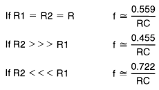
Oscillator Components:
For all ranges of frequency a 100kΩ resistor is recommended and the capacitor is selected from the equation:

Reference Voltage:
The analog input required to generate full scale output (2000 counts) is: VlN = 2VREF. Thus, for the 200mV and 2V scale, VREF should equal 100mV and 1V, respectively.
Development of PCB:
Step 1: Circuit Diagram and Components required
1. 7-Segment Display Common Anode Qty. 3
2. ICL7107, and IC Base 40 Pin
3. LM35 Temperature Sensor
4. LM7805
5. 1N4007
6. Other Capacitors and Resistors

Download PDF Circuit Diagram
Step 2: PCB Layout
Download PCB Layout pdf
Download Component Placement Diagram pdf

Step 3: Assemble Components and Test the circuit
1. Comment if you have any questions.
2. Like, Share, Follow us on Google+
The Intersil ICL7106 and ICL7107 are high performance, low power, 31/2 digit A/D converters. Included are seven segment decoders, display drivers, a reference, and a clock. The ICL7106 is designed to interface with a liquid crystal display (LCD) and includes a multiplexed backplane drive; the ICL7107 will directly drive an instrument size light emitting diode (LED) display. The ICL7106 and ICL7107 bring together a combination of high accuracy, versatility, and true economy. It features autozero to less than 10μV, zero drift of less than 1μV/oC, input bias current of 10pA (Max), and rollover error of less than one count. True differential inputs and reference are useful in all systems, but give the designer an uncommon advantage when measuring load cells, strain gauges and other bridge type transducers. Finally, the true economy of single power supply operation (ICL7106), enables a high performance panel meter to be built with the addition of only 10 passive components and a display.

Working:
We have designed basic 99.9mV DC Voltmeter using design steps given in data sheets. It displays 3 digits i.e. 99.9mV maximum. Actually ICL7107 have 3 and 1/2 Display we are not
using 1/2(half) display. Reference voltage of 100mV is generated using 1.2 V Zener and Variable resistor forms a voltage divider. Input is divided by 10K and 1.1KOhm resistor (divide by 10) to get proportional temperature scale. Block diagram gives clear idea about how it works.

Components Value Selection:
Integrating Resistor:
Both the buffer amplifier and the integrator have a class A output stage with 100μA of quiescent current. They can supply 4μA of drive current with negligible nonlinearity. The integrating resistor should be large enough to remain in this very linear region over the input voltage range, but small enough that undue leakage requirements are not placed on the PC board. For 2V full scale, 470kΩ is near optimum and similarly a 47kΩ for a 200mV scale. Select 47KΩ (Resistor Connected at Pin 28) Vbuf
Integrating Capacitor:
The integrating capacitor should be selected to give the maximum voltage swing that ensures tolerance buildup will not saturate the integrator swing (approximately. 0.3V from either supply). In the ICL7106 or the ICL7107, when the analog COMMON is used as a reference, a nominal +2V fullscale integrator swing is fine. For the ICL7107 with +5V supplies and analog COMMON tied to supply ground, a ±3.5V to +4V swing is nominal. For three readings/second (48kHz clock) nominal values for ClNT are 0.22μF and 0.10μF, respectively. Of course, if different oscillator frequencies are used, these values should be changed in inverse proportion to maintain the same output swing. An additional requirement of the integrating capacitor is that it must have a low dielectric absorption to prevent roll-over errors. While other types of capacitors are adequate for this application, polypropylene capacitors give undetectable errors at reasonable cost. (Capacitor Connected at Pin 27 Select 0.22uF)
Auto-Zero Capacitor (Pin 29):
The size of the auto-zero capacitor has some influence on the noise of the system. For 200mV full scale where noise is very important, a 0.47μF capacitor is recommended. On the 2V scale, a 0.047μF capacitor increases the speed of recovery from overload and is adequate for noise on this
scale.
Reference Capacitor: (Pin 34, 33):
A 0.1μF capacitor gives good results in most applications. However, where a large common mode voltage exists (i.e., the REF LO pin is not at analog COMMON) and a 200mV scale is used, a larger value is required to prevent roll-over error. Generally 1μF will hold the roll-over error to 0.5 count in this instance.
Oscillator Components:
For all ranges of frequency a 100kΩ resistor is recommended and the capacitor is selected from the equation:
Reference Voltage:
The analog input required to generate full scale output (2000 counts) is: VlN = 2VREF. Thus, for the 200mV and 2V scale, VREF should equal 100mV and 1V, respectively.
Development of PCB:
Step 1: Circuit Diagram and Components required
1. 7-Segment Display Common Anode Qty. 3
2. ICL7107, and IC Base 40 Pin
3. LM35 Temperature Sensor
4. LM7805
5. 1N4007
6. Other Capacitors and Resistors

Download PDF Circuit Diagram
Step 2: PCB Layout
Download PCB Layout pdf
Download Component Placement Diagram pdf

Step 3: Assemble Components and Test the circuit
1. Comment if you have any questions.
2. Like, Share, Follow us on Google+