CMOS Oscillators Design Fundamental:
This tutorial describes several square wave oscillators that can be built using CMOS logic elements. These circuits offer the following advantages:
• Guaranteed startability
• Relatively good stability with respect to power supply variations
• Operation over a wide supply voltage range (3V to 15V)
• Operation over a wide frequency range from less than 1 Hz to about 15 MHz
• Low power consumption
• Easy interface to other logic families and elements including TTL
LOGICAL OSCILLATORS
 The frequency of oscillation will be determined by the total propagation delay through the ring and is given by the following equation.
 Where:
f = frequency of oscillation
Tp = Propagation delay per gate
n = number of gates
This is not a practical oscillator, of course, but it does illustrate the maximum frequency at which such an oscillator will run. All that must be done to make this a useful oscillator is to slow it down to the desired frequency. Methods of doing this are described later. To determine the frequency of oscillation, it is necessary to examine the propagation delay of the inverters. CMOS propagation delay depends on supply voltage and load capacitance. Several curves for propagation delay for Fairchild’s 74C line of CMOS gates are reproduced in Figure 3. From these, the natural frequency of oscillation of an odd number of gates can be determined. An example may be instructive. Assume the supply voltage is 10V. Since only one input is
driven by each inverter, the load capacitance on each inverter is at most about 8 pF. Examine the curve in Figure 3c that is drawn for VCC = 10V and extrapolate it down to 8 pF. We see that the curve predicts a propagation delay of about 17 ns. We can then calculate the frequency of oscillation for three inverters using the expression mentioned above.
STABLE RC OSCILLATOR:


This tutorial describes several square wave oscillators that can be built using CMOS logic elements. These circuits offer the following advantages:
• Guaranteed startability
• Relatively good stability with respect to power supply variations
• Operation over a wide supply voltage range (3V to 15V)
• Operation over a wide frequency range from less than 1 Hz to about 15 MHz
• Low power consumption
• Easy interface to other logic families and elements including TTL
Several RC oscillators and two crystal controlled oscillators are described. The stability of the RC oscillator will be sufficient for the bulk of applications; however, some applications will probably require the stability of a crystal. Some applications that require a lot of stability are:
1. Timekeeping over a long interval. A good deal of stability is required to duplicate the performance of an ordinary wrist watch (about 12 ppm). This is, of course, obtainable with a crystal. However, if the time interval is short and/or the resolution of the timekeeping device is relatively large, an RC oscillator may be adequate. For example: if a stopwatch is built with a resolution of tenths of seconds and the longest interval of interest is two minutes, then an accuracy of 1 part in 1200 (2 minutes x 60 seconds/minute x 10 tenth/second) may be acceptable since any error is less than the resolution of the device.
2. When logic elements are operated near their specified limits. It may be necessary to maintain clock frequency accuracy within very tight limits in order to avoid exceeding the limits of the logic family being used, or in which the timing relationships of clock signals in dynamic MOS memory or shift register systems must be preserved.
3. Baud rate generators for communications equipment.
4. Any system that must interface with other tightly specified systems. Particularly those that use a “handshake” technique in which Request or Acknowledge pulses must be of specific widths.
LOGICAL OSCILLATORS
Before describing any specific circuits, a few words about logical oscillators may clear up some recurring confusion. Any odd number of inverting logic gates will oscillate if they are tied together in a ring as shown in Figure 1. Many beginning logic designers have discovered this (to their chagrin) by inadvertently providing such a path in their designs. However, some people are confused by the circuit in Figure 1 because they are accustomed to seeing sinewave oscillators implemented with positive feedback, or amplifiers withnon-inverting gain. Since the concept of phase shift becomes a little strained when the inverters remain in their linear region for such a short period, it is far more straightforward to analyze the circuit from the standpoint of ideal switches with finite propagation delays rather than as amplifiers with 180° phase shift. It then becomes obvious that a “1” chases itself around the ring and the network oscillates.

f = frequency of oscillation
Tp = Propagation delay per gate
n = number of gates
This is not a practical oscillator, of course, but it does illustrate the maximum frequency at which such an oscillator will run. All that must be done to make this a useful oscillator is to slow it down to the desired frequency. Methods of doing this are described later. To determine the frequency of oscillation, it is necessary to examine the propagation delay of the inverters. CMOS propagation delay depends on supply voltage and load capacitance. Several curves for propagation delay for Fairchild’s 74C line of CMOS gates are reproduced in Figure 3. From these, the natural frequency of oscillation of an odd number of gates can be determined. An example may be instructive. Assume the supply voltage is 10V. Since only one input is
driven by each inverter, the load capacitance on each inverter is at most about 8 pF. Examine the curve in Figure 3c that is drawn for VCC = 10V and extrapolate it down to 8 pF. We see that the curve predicts a propagation delay of about 17 ns. We can then calculate the frequency of oscillation for three inverters using the expression mentioned above.
STABLE RC OSCILLATOR:
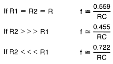
Figure 2 illustrates a useful oscillator made with three inverters. Actually, any inverting CMOS gate or combination of gates could be used. This means left over portions of gate packages can be often used. The duty cycle will be close to 50% and will oscillate at a frequency that is given by the following expression.
The following three special cases may be useful.
A SINGLE SCHMITT TRIGGER MAKES AN OSCILLATOR:
Figure 6 illustrates an oscillator made from a single Schmitt trigger. Since the MM74C14 is a hex Schmitt trigger, this oscillator consumes only one sixth of a package. The remaining 5 gates can be used either as ordinary inverters like the MM74C04 or their Schmitt trigger characteristics can be used to advantage in the normal manner. Assuming these five inverters can be used elsewhere in the system, Figure 6 must represent the ultimate in low gate count oscillators.
If these thresholds were constant percentages of VCC over the supply voltage range, the oscillator would be insensitive to variations in VCC. However, this is not the case. The thresholds of the Schmitt trigger vary enough to make the oscillator exhibit a good deal of sensitivity to VCC.


No comments:
Post a Comment