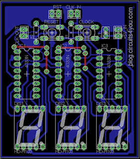
Aim of this project is very simple it counts Objects or Pulses from IR proximity detector. Maximum count is 999. It can be reset at any point and pulses for counting can be given from various sensors, such as IR sensor or LDR circuit.
In this project we are using CD4033 consists of a 5 stage Johnson decade counter and an output decoder which converts the Johnson code to a 7 segment decoded output for driving one stage in a numerical
display. This device is particularly advantageous in display applications where low power dissipation and/or low package count is important. A high RESET signal clears the decade counter to its zero count. The counter is advanced one count at the positive clock signal transition if the CLOCK INHIBIT signal is low. Counter advancement via the clock line is inhibited when the CLOCK INHIBIT signal is high. The CLOCK INHIBIT signal can be used as a negative-edge clock if the clock line is held high. Antilock gating is provided on the JOHNSON counter, thus assuring proper counting sequence. The CARRY-OUT (Cout) signal completes one cycle every ten CLOCK INPUT cycles and is used to clock the succeeding decade directly in a multi-decade counting chain. The seven decoded outputs (a, b, c, d, e, f, g) illuminate the
proper segments in a seven segment display device used for representing the decimal numbers 0 to 9. The 7 segment outputs go high on selection.
Step 1: Components Required
1. 7-Segment Display Common Cathode Qty. 3
2. CD4033 Qty. 3
3. 16-Pin IC base for the IC
4. Resistor 10K
5. Switches or any pulse input that can be given to input pins
Step 2: PCB Development
Step 3: Test The Circuit
1. Circuit Works on +5V.
2. Connect +5V Supply
3. Press Clock Switch and observe that count gets incremented
4. Press Reset Switch to reset the count
5. Connect proximity sensor to clock in. You can connect any sensor that gives TTL level pulses.
6. Follow us on Google+, Facebook
7. If you have any questions please comment. If you want any new circuit comment it.


no seria mejor con un 7490 o 7492,93?
ReplyDelete