The aim of this project is to demonstrate use of Vibration sensor to detect vehicle theft and also GSM module applications.
This project has GSM technology and Vehicle anti-theft system with vehicle ignition controlling technique. Whenever car owner removes key from the ignition lock at that system is turned on. We have provided vibration sensor with this project, which is similar to piezoelectric sensor. When vibrations are detected, SMS is sent to the owner of the car. When car owner sends back sms to project then the engine is stopped. We can provide a Relay to turn odd engine.
Components Required:
1. GSM Modem
2. Arduino
3. 16x2 LCD
4. Vibration Sensor

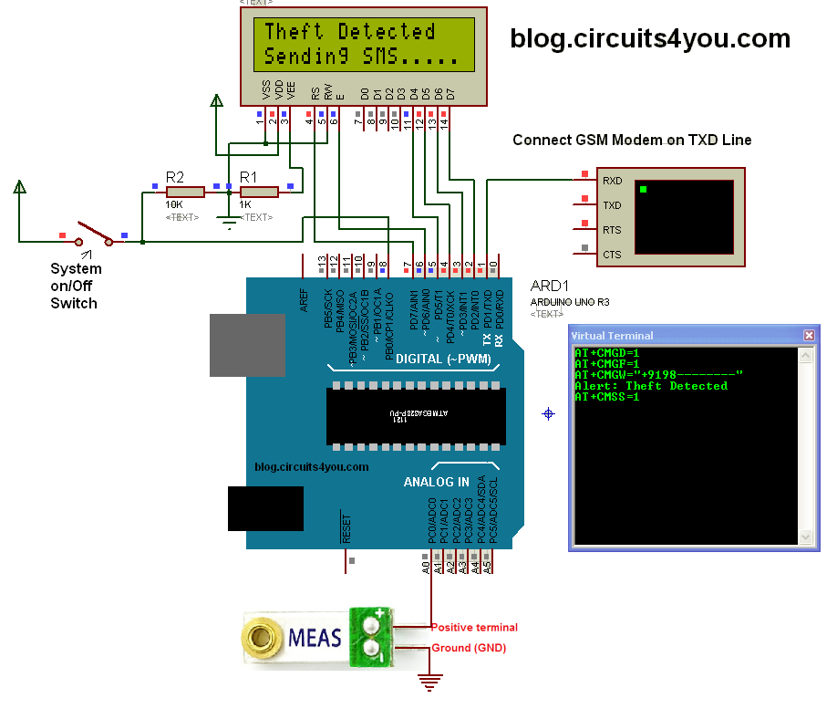
Step 1: Circuit Connections
Step 2: Programming
enter your mobile number in sendSMS routine
/*
Vehicle Security System using GSM with SMS Alert
 Blog.Circuits4You.com 2016

 Demonstrates the use of PIR Motion sensor and GSM Module.  The Project
 generate SMS when motion is detected on PIR Sensor

 PIR Sensor is connected to Arduino Pin 8 and GSM Module on Serial Communication
 Lines, Remove GSM Module While Programming.

  The circuit:
 * LCD RS pin to digital pin 12
 * LCD Enable pin to digital pin 11
 * LCD D4 pin to digital pin 5
 * LCD D5 pin to digital pin 4
 * LCD D6 pin to digital pin 3
 * LCD D7 pin to digital pin 2
 * LCD R/W pin to ground
 */

// include the library code:
#include <LiquidCrystal.h>

// initialize the library with the numbers of the interface pins
LiquidCrystal lcd(7, 6, 5, 4, 3, 2);

const int Switch=8;
cont int Sensor=0;

void setup() {
  pinMode(PIR,INPUT);
  Serial.begin(9600);
  // set up the LCD's number of columns and rows:
  lcd.begin(16, 2);
}

void loop() {
  // Print a message to the LCD.
    if(digitalRead(Switch)==HIGH)
    {
        lcd.setCursor(0, 0);
        lcd.print("Security System ");
        lcd.setCursor(0, 1);
        lcd.print("   Aactivated    ");

      if(analogRead(A0)>500)      //Set vibration detection threshould 500
      {
          // Print a message to the LCD.
          lcd.setCursor(0, 0);
          lcd.print("Theft Detected  ");
          lcd.setCursor(0, 1);
          lcd.print("Sending SMS.....");

          //Turn on Alarm here
          digitalWrite(13,HIGH);    //Turn on Alarm connect buzzer to this pin through transistor

          sendSMS();
          delay(5000);
      }
      else
      {
        digitalWrite(13,LOW);    //Turn off alarm
      }
    }
    else
    {
        lcd.setCursor(0, 0);
        lcd.print("Security System ");
        lcd.setCursor(0, 1);
        lcd.print("   Deactivated    ");
    }
}

void sendSMS()
{
     Serial.println("AT+CMGD=1");    //Delete privious sent SMS
     delay(1000);

     Serial.println("AT+CMGF=1");   //Set SMS configuration
     delay(1000);

     Serial.print("AT+CMGW=");          //Write New SMS
     Serial.write(34);                  //Double quotes ASCII Code
     Serial.print("+9198--------");         //Enter Your Mobile number
     Serial.write(34);
     Serial.println();                  //Send Crrige return
     delay(1000);

     Serial.println("Alert: Theft Detected");
     delay(1000);

     Serial.write(26); //Cntrl+Z
     delay(1000);
     delay(1000);

     Serial.println("AT+CMSS=1");      //Send SMS from memory location 1
     delay(4000);
}
Step 3: Testing
1. Turn on the switch i.e connected to Pin 8 of arduino
2. LCD will display "System Activated"
3. Give some vibration to vibration sensor
4. LCD will show "Sending SMS"
5. Check that you got the sms
6. Do not forget to change mobile number in code
1. Turn on the switch i.e connected to Pin 8 of arduino
2. LCD will display "System Activated"
3. Give some vibration to vibration sensor
4. LCD will show "Sending SMS"
5. Check that you got the sms
6. Do not forget to change mobile number in code


No comments:
Post a Comment