Showing posts with label Arduino Projects. Show all posts

Monday, April 11, 2016

Low cost continuous pricision liquid level measurement using arduino

The purpose of this turorial is to demonstrate an innovative approach for low cost continuous liquid level monitoring based on MPX5010DP differential pressure sensor. Most of the traditional measuring systems were designed and implemented by complicated hardware circuitry. It made the product expensive, with low functionality and with limited precision. With virtual measurement technology, more of the instrument can be substituted by software. Using this approach the cheaper and more versatile measurement system can be developed. The method for obtaining liquid level with one differential pressure sensors MPX5010DP is suggested and considered. Some basic considerations about the modern integrated pressure sensors and some aspects concerning their capability for liquid level measurement are done. Finally, a prototype of a liquid level monitoring system based on integrated differential pressure sensors, arduino board and LabVIEW environment is developed for measuring liquid level accurately at distances up to 10 metres. In order to illustrate flexibility of the designed system the front panel of the developed virtual instrument is presented. Measurements carried out in laboratory show that the accuracy of some millimetres could be achieved.

Hydrostatic pressure and level sensing theory:
There are three types of pressure measurement. Absolute pressure does include atmospheric
pressure, and is measured relative to vacuum. Differential pressure is the difference between two pressures. Gage pressure is a form of differential pressure measurement in which atmospheric pressure is used as the reference. A pressure transmitter can be used to determine the liquid level in a tank, well, river or other body of liquid. If a pipe is placed vertically, with one end dipped into a liquid and the upper end of the pipe is closed off and some air volume is trapped.

Components Required:
1. Arduino Uno or any internal ADC microcontroller
2. MPX5010DP Pressure sensor
3. LCD Display 16x2
4. Water purifier pipe 1 mtr

Step 1: Circuit Connections

Pin Diagram of MPX5010DP:


Setup Diagram for Level Measurement:
Arduino Level measurement


Step 2: Programming (Arduino Code for Level Measurement)


/*=================================================
Blog.circuits4you.com - 2016
Pricision Liquid Level measurement using arduino
=================================================*/
#include <LiquidCrystal.h>

LiquidCrystal lcd(12, 11, 10, 5, 4, 3, 2);
int Level;

void setup()
{
  lcd.begin(16,1);
}

void loop() 
{
  Level = analogRead(A0)-45;  //Sensor is having some offset so do some calibration here
  
  lcd.setCursor(0 , 0);
  lcd.print("Liquid Level:");
  lcd.print(Level);
  lcd.print(" Ltr");
  delay(1000);
}

Step 3:Test your liquid level measurement in water
1. Put the pipe in water as you dip it in water you will see the level of water.
2. The principle of operation is when liquid level rises the trapped air in pipe generates pressure on sensor that is proportional to the liquid level.
3. Take care of proper sealing at the joint of sensor and pipe.
4. You can use water purifier pipe.

For more interesting projects visit Project section

Text to Speech on arduino

Give your project a voice! Without Text-to-Speech Module, Arduino TTS library makes it possible, voice synthesizer that converts a stream of digital text into retro (robot) speech. Its simple needs only external LM385 amplifier with arduino Uno, No special components or shields required. Thanks to Gabriel Petrut and Clive Webster for making this thing.
Application Ideas:
  • Reading Internet-based data streams (such as e-mails or Twitter feeds)
  • Conveying status or sensor results from robots, scientific equipment, or industrial machinery
  • Language learning or speech aids for educational environments

Components required:
1. Arduino Uno
2. LM386
3. Speaker
4. Capacitors and few resistors as shown in circuit

Step: 1 Circuit Diagram

Text to Speech arduino (TTS)

Step: 2 Library download

Download library from here


Step: 3 Sample Code

This program and library works only with Arduino 1.0 version

Program:
/*
  Text To Speech syntesis library
  Copyright (c) 2008 Clive Webster.  All rights reserved.
  Nov. 29th 2009 - Modified to work with Arduino by Gabriel Petrut.
*/

/*
  The Text To Speech library uses Timer1 to generate the PWM
  output on digital pin 10. The output signal needs to be fed
  to an RC filter then through an amplifier to the speaker.
*/

#include <TTS.h>

// Media pins
#define ledPin 13       // digital pin 13                          

// Variables
char text [50];
boolean state=0;

TTS text2speech;  // speech output is digital pin 10

void setup() { 
  //media
  pinMode(ledPin, OUTPUT); 
}

//================================================================
// Main Loop
//================================================================
void loop(){
    state = !state;
    digitalWrite(ledPin, state);
    Test_Speech();
    delay(1000);          // delay a second
}  
//================================================================


void Test_Speech() {
 text2speech.setPitch(6); //higher values = lower voice pitch
 strcpy(text, "Hello  master! How are you doin?");
 text2speech.say(text);
 delay(500);
 text2speech.setPitch(1); //lower values = higher voice pitch
 strcpy(text, "I am fine, thankyou.");
 text2speech.say(text);
}


Step: 4 Test your creation

For more interesting projects click here

Arduino now speak what you have given to speak.....enjoy
for queries and questions please comment..


Saturday, April 2, 2016

Wireless Serial using nRF24L01+

This project is very useful in many application where wireless reliable serial communication is required. It give bidirectional communication, You need to have same code in both arduino, no need of separate configuration for receiver or transmitter. It is more advantageous and cost saving than using Xbee, Zegbee Modules.

This circuit is consists of Arduino Pro Mini 3.3V 8MHz and nRF24L01+ RF Module, this make it very low cost and reliable, it can communicate at longer distances when we use nRF24L01+ PA LNA module.

The code is done with most advance possible conditions here I am using custom serial software routine instead of arduino serial to make possible to have 256bytes of serial buffer. arduino have only 64 bytes of serial buffer for longer serial data use of internal buffer causes problems so I made my own serial rutine

Let's look at its advantages nRF24L01+ modules are very cheap and low power consuming, you can power your circuit using 3V battery also, that's why I am using Arduino Pro Mini 3.3V 8MHz, you can use any arduino board, only take care that supply to nRF24L01+ module must be 3.3V, nRF24L01+ can take 5V on its IO lines so no need to have any level conversion circuits.

Applications of this projects are limitless you can use it for your robotic applications, remote sensing, wireless remote control, RC air craft as nRF24L01+ PA LNA module can give open air 1000 meter range.

Components required:
1. nRF24L01+ Quantity 2.
2. Two arduino boards.

Introduction to nRF24L01+:
The nRF24L01+ is a single chip 2.4GHz transceiver with an embedded baseband protocol engine, suitable for ultra low power wireless applications. The nRF24L01+ is designed for operation in the world wide ISM frequency band at 2.400-2.4835GHz.

To design a radio system with the nRF24L01+, you simply need an microcontroller and a few external passive components.

You can operate and configure the nRF24L01+ through a Serial Peripheral Interface (SPI). The register map, which is accessible through the SPI, contains all configuration registers in the nRF24L01+ and is accessible in all operation modes of the chip.

The embedded baseband protocol engine is based on paket communication and supports various modes from manual operation to advanced autonomous protocol operation.

Internal FIFOs ensure a smooth data flow between the radio front end and the system's microcontroller. Enhanced Shock-Burst reduces system cost by handling all the high speed link layer operations.

The radio front end uses GFSK modulation. It has user configurable parameters like frequency channel, output power and air data rate. nRF24L01+ supports an air data rate of 250kbps, 1Mbps and 2Mbps. The high air data rate combined with two power saving modes make the nRF24L01+ very suitable for ultra low power designs.


Step 1: Circuit Connections of nRF24L01+ with Arduino Pro Mini you can use Arduino Uno also with same code and connections

Wireless Serial Communication circuit


Step 2: Programming
RF24 library is required you can download it from arduino web site
You can modify the program if you want to control your robotics with wireless serial.
At serial send subroutine wireless received  data is sent to serial, and when serial data is received it is put into buffer then transmitter through nRF24L01+

Use same code in both arduino boards.
//Blog.Circuits4you.com Wireless serial communication
//26-Jan-2015
//DO NOT FORGET BAUD RATE SETTINGS FOR 8MHz MINI PRO

#include <avr/io.h>
#include <avr/interrupt.h>
#include <SPI.h>
#include "nRF24L01.h"
#include "RF24.h"

RF24 radio(9,10);
const uint64_t pipes[2] = { 0xDEDEDEDEE7LL, 0xDEDEDEDEE9LL };

char SerialBuffer[256] = "";
char RecvPayload[128] = "";
int i,TimeOut=10,dataBufferIndex=0;

void setup() {
  radio.begin();
  
  radio.setDataRate(RF24_250KBPS);
  radio.setPALevel(RF24_PA_MAX);
  radio.setChannel(70);
  
  radio.enableDynamicPayloads();
  radio.setRetries(15,15);
  radio.setCRCLength(RF24_CRC_16);

  radio.openWritingPipe(pipes[0]);
  radio.openReadingPipe(1,pipes[1]);  
  
  radio.startListening();
   
  
  USART_Init();  
  SREG=0x80;  
  delay(500);
}

void loop() {
  nRF_receive();  
  
  if(TimeOut==0 && dataBufferIndex>0)
  {
    serial_receive();        // Send this buffer out to radio
  }
  else
  {
    TimeOut--;
  }
}

void USART_vSendByte(char u8Data)
{
  // Wait if a byte is being transmitted
  while((UCSR0A & (1<<UDRE0)) == 0);
  // Transmit data
  UDR0 = u8Data; 
}

/****************************************************************************************/
/*                                                                          USART INIT                                        */
/****************************************************************************************/
void USART_Init()
{
  /*Set baud rate */
  UBRR0H = 0;
  UBRR0L = 51;  //103 @ 16MHz  51 @ 8MHz
  //Set double speed enabled 
  UCSR0A |= (1<<U2X0);
   
  /*Enable receiver and transmitter */
  UCSR0B = (1<<RXEN0)|(1<<TXEN0) | (1<<RXCIE0);
  /* Set frame format: 8data, 2stop bit */
  UCSR0C = (1<<USBS0)|(3<<UCSZ00);
}
/****************************************************************************************/
/*           USART ISR                                         */
/****************************************************************************************/
SIGNAL(USART_RX_vect)
{
        char incomingByte = UDR0;
        SerialBuffer[dataBufferIndex++]=incomingByte;    
        TimeOut=2000;
 sei();
 return; 
}
/****************************************************************************************/
/*                RF Receive                                                            */
/****************************************************************************************/
void nRF_receive(void) {
  int len = 0;
  if ( radio.available() ) {
      bool done = false;
      while ( !done ) {
        len = radio.getDynamicPayloadSize();
        done = radio.read(&RecvPayload,len);
        delay(5);
      }
  
    RecvPayload[len] = 0; // null terminate string
    
     for(i=0;i<len;i++)
    {
      USART_vSendByte(RecvPayload[i]);      
    }
    RecvPayload[0] = 0;  // Clear the buffers
  }  

}

void serial_receive(void)
{
        char SendPayLoad[32];
        // swap TX & Rx addr for writing
        radio.openWritingPipe(pipes[1]);
        radio.openReadingPipe(0,pipes[0]);  
        radio.stopListening();
        
        if(dataBufferIndex<31)      //as nRF24L02 have only 32 byte of buffer to send more bytes it need to be splitted
        {          
          bool ok = radio.write(&SerialBuffer,dataBufferIndex);
        }
        else  
        {
          for(i=0;i<30;i++)
          {
            SendPayLoad[i]=SerialBuffer[i];
          }
            bool ok = radio.write(&SendPayLoad,30);    //First 30 Bytes are sent
          
          if((dataBufferIndex-30)<31)    //If remainging bytes are less than 31
          {
              for(i=0;i<(dataBufferIndex-30);i++)
              {
                SendPayLoad[i]=SerialBuffer[i+30];
              }
            bool ok = radio.write(&SendPayLoad,(dataBufferIndex-30));    //Remaining Bytes are sent
          }
          else                            //Remaining bytes are more than 31 i.e total is greater than 60
          {
                      for(i=0;i<30;i++)
                      {
                        SendPayLoad[i]=SerialBuffer[i+30];    
                      }
                        bool ok = radio.write(&SendPayLoad,30);    //60 Bytes are sent
                      
                      if((dataBufferIndex-60)<31)    //If remainging bytes are less than 31 
                      {
                          for(i=0;i<(dataBufferIndex-30);i++)
                          {
                            SendPayLoad[i]=SerialBuffer[i+60];
                          }
                        bool ok = radio.write(&SendPayLoad,(dataBufferIndex-60));    //Remaining Bytes are sent
                      }
          }
        }
        // restore TX & Rx addr for reading       
        radio.openWritingPipe(pipes[0]);
        radio.openReadingPipe(1,pipes[1]); 
        radio.startListening();  

        SerialBuffer[0] = 0;  // Clear the buffers
        dataBufferIndex = 0;
} // end serial_receive()  

#ifndef min
#define min(a,b) ( (a) < (b) ? (a) : (b) )
#endif
 
void mid(const char *src, size_t start, size_t length, char *dst, size_t dstlen)
{       size_t len = min( dstlen - 1, length);
 
        strncpy(dst, src + start, len);
        // zero terminate because strncpy() didn't ? 
        if(len < length)
                dst[dstlen-1] = 0;
}

Step 3: Testing of Wireless Serial
1. Open serial terminal of both boards
2. What ever you send from one board serial terminal will appear it in other serial terminal and vice versa.
3. Points to remember Wireless nRF24L01+ module will not work if they are placed very close, at least have 2 to 3 meter distance between them to work properly
4. Check baud rate in serial init routine, I think I am using 19200 BAUD it depends on your board 8MHz or 16MHz

Friday, April 1, 2016

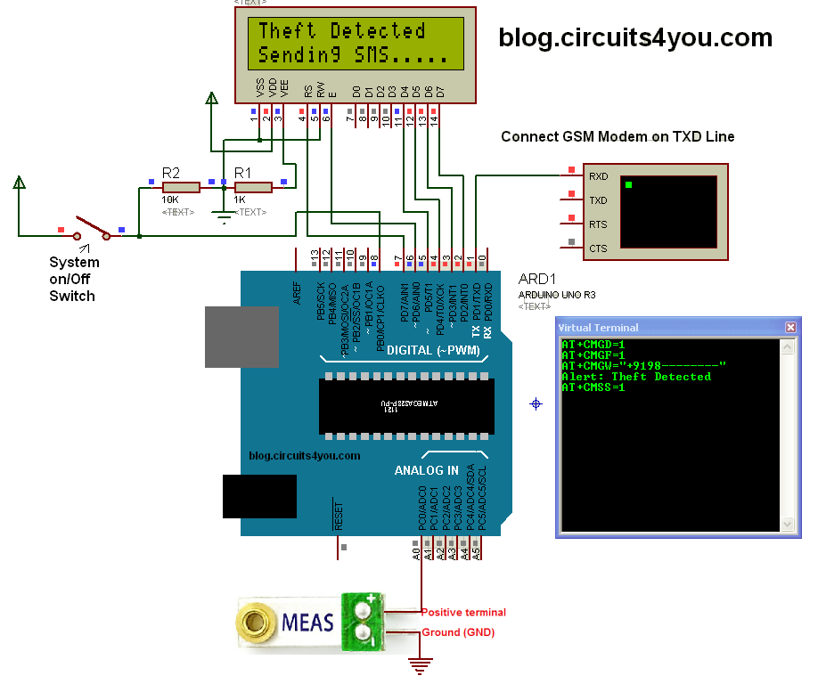
Vehicle anti-theft system using GSM modem and vibration sensor

The aim of this project is to demonstrate use of Vibration sensor to detect vehicle theft and also GSM module applications.

This project has GSM technology and Vehicle anti-theft system with vehicle ignition controlling technique. Whenever car owner removes key from the ignition lock at that system is turned on. We have provided vibration sensor with this project, which is similar to piezoelectric sensor. When vibrations are detected, SMS is sent to the owner of the car. When car owner sends back sms to project then the engine is stopped. We can provide a Relay to turn odd engine.

Components Required:
1. GSM Modem
2. Arduino
3. 16x2 LCD

4. Vibration Sensor

Step 1: Circuit Connections


Step 2: Programming

enter your mobile number in sendSMS routine

/*
Vehicle Security System using GSM with SMS Alert
 Blog.Circuits4You.com 2016

 Demonstrates the use of PIR Motion sensor and GSM Module.  The Project
 generate SMS when motion is detected on PIR Sensor

 PIR Sensor is connected to Arduino Pin 8 and GSM Module on Serial Communication 
 Lines, Remove GSM Module While Programming. 
  
  The circuit:
 * LCD RS pin to digital pin 12
 * LCD Enable pin to digital pin 11
 * LCD D4 pin to digital pin 5
 * LCD D5 pin to digital pin 4
 * LCD D6 pin to digital pin 3
 * LCD D7 pin to digital pin 2
 * LCD R/W pin to ground
 */

// include the library code:
#include <LiquidCrystal.h>

// initialize the library with the numbers of the interface pins
LiquidCrystal lcd(7, 6, 5, 4, 3, 2);

const int Switch=8;
cont int Sensor=0;

void setup() {
  pinMode(PIR,INPUT);
  Serial.begin(9600);
  // set up the LCD's number of columns and rows: 
  lcd.begin(16, 2);
}

void loop() {
  // Print a message to the LCD.  
    if(digitalRead(Switch)==HIGH)
    {     
        lcd.setCursor(0, 0);
        lcd.print("Security System ");
        lcd.setCursor(0, 1);
        lcd.print("   Aactivated    ");

      if(analogRead(A0)>500)      //Set vibration detection threshould 500
      {
          // Print a message to the LCD.
          lcd.setCursor(0, 0);
          lcd.print("Theft Detected  ");
          lcd.setCursor(0, 1);
          lcd.print("Sending SMS.....");
          
          //Turn on Alarm here
          digitalWrite(13,HIGH);    //Turn on Alarm connect buzzer to this pin through transistor
          
          sendSMS();
          delay(5000);
      }
      else
      {
        digitalWrite(13,LOW);    //Turn off alarm
      }
    }
    else
    {
        lcd.setCursor(0, 0);
        lcd.print("Security System ");
        lcd.setCursor(0, 1);
        lcd.print("   Deactivated    ");
    }
}

void sendSMS()
{
     Serial.println("AT+CMGD=1");    //Delete privious sent SMS
     delay(1000);
          
     Serial.println("AT+CMGF=1");   //Set SMS configuration
     delay(1000);
     
     Serial.print("AT+CMGW=");          //Write New SMS
     Serial.write(34);                  //Double quotes ASCII Code
     Serial.print("+9198--------");         //Enter Your Mobile number
     Serial.write(34);
     Serial.println();                  //Send Crrige return
     delay(1000);
     
     Serial.println("Alert: Theft Detected");
     delay(1000);

     Serial.write(26); //Cntrl+Z
     delay(1000);
     delay(1000);

     Serial.println("AT+CMSS=1");      //Send SMS from memory location 1
     delay(4000);
}


Step 3: Testing

1. Turn on the switch i.e connected to Pin 8 of arduino

2. LCD will display "System Activated"
3. Give some vibration to vibration sensor
4. LCD will show "Sending SMS"
5. Check that you got the sms
6. Do not forget to change mobile number in code

Sunday, May 31, 2015

Bluetooth Controlled Electrical Appliances

Bluetooth controlled Lights, Electrical Equipment, Smart Phone Based Appliances Control
Bluetooth Based Room Automation
Arduino Bluetooth appliances control

Android app for arduino control


Bluetooth Based Home automation using android

Step by Step Guide: Next >>


Tuesday, May 19, 2015

LM35 Temperature Sensor Interfacing with Arduino


Description:

LM35 is a precision temperature sensor with its output proportional to the temperature (in oC). With LM35, temperature can be measured more accurately than with a thermistor. It also possess low self heating and does not cause more than 0.1 oC temperature rise in still air.   
The operating temperature range is from -55°C to 150°C. The output voltage varies by 10mV in response to ambient temperature, its scale factor is 0.01V/ oC.

Connection Diagram:

temp = (1.1 * analogRead(tempPin) * 100.0) / 1024;
To change aRef to 1.1V, you use the command "analogReference(INTERNAL);"

Code:


float tempC;
int reading;
int tempPin = 0;

void setup()
{
  analogReference(INTERNAL);
  Serial.begin(9600);
}

void loop()
{
  reading = analogRead(tempPin);
  tempC = reading / 9.31;
  Serial.print("Temprature= ");
  Serial.print(tempC);
  Serial.print("*C");
  Serial.println();
  delay(1000);
}


Output:
    Click on Tools >> Serial Monitor in Arduino Software